利用DrawCommand绘制自定义的几何体
骚年,你相信吗?你学了 DrawCommand 的话,利用 Cesium 就没有你画不了的几何体(童叟无欺.jpg)。每款渲染引擎一定都提供了根据顶点数组数据来渲染模型的能力, Cesium 也不例外,PS:一般情况下,我们认为顶点数组数据包括但不限于:顶点坐标,顶点纹理,顶点法线,顶点切线…
下面我们介绍 DrawCommand 是干嘛的,以及怎么使用。最后,我们会创建一个 CustomPrimitive 模块来承载我们自定义的模型,并以立方体的数据为例,来进行展示。(这样一看,是不是如果我们有 OBJ 模型,只要将对应顶点数据和纹理数据解析出来就可以进行渲染了呢)。
简介
在 Cesium 中, DrawCommand 指令是将装配好的模型数据进行绘制的核心命令, Cesium 维护了一个命令列表来进行不同通道(透明、不透明等)数据的绘制,我们可以认为每一个 Primitive 都具备自己的 DrawCommand ,并且会在自己实例的 update 方法中进行命令更新,然后推入命令列表当中。除了 Cesium 中的 Primitive ,像 Skybox 和 Sun 这些模块也使用 DrawCommand 绘制的(当然我这句话是废话, DrawCommand 是 Cesium 渲染的命令,不用它用谁)。
开发
自定义几何体模块架构
该板块的设计遵循了 Primitive 由 Geometry 和 Material 构成的设计理念:
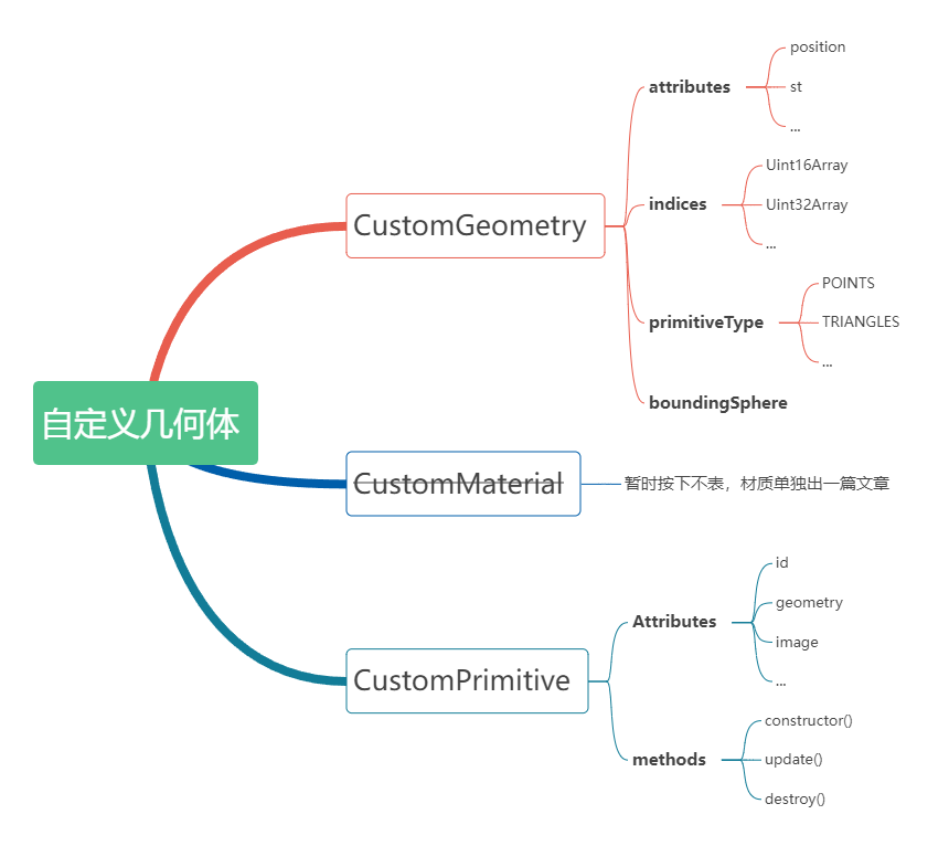
该板块构建 CustomGeometry , CustomMaterial 和 CustomPrimitive 这三个类文件,不过由于本人对 Cesium 中的材质还不了解,对于本文中纹理的设置,我们先集成在 CustomPrimitive 当中,故我们只需按关注另外两个类文件即可( Cesium 的 Material 会单独写一篇文章,疯狂挖坑)。
CustomGeometry
写在前面,如果想我门自定义的 Geometry 能够被正常使用,那么下面这几个属性是必不可少的: GeometryAttributes 、 PrimitiveType 和 BoundingSphere 。
CustomGeometry 板块要求用户输入模型的数据,即 position , st , normal 和 indices 等类型数组数据(本DEMO仅在代码中写了位置和纹理坐标数据的处理)。要注意的是, indices 并不属于顶点数据哦。属于VAO(Vertex Array Objec)的属性都被归到了 attributes 下面,它们和 indices 底层创建 Buffer 的方法也有区别。还要注意的是 indices 选取的类型,可以根据顶点的数量来进行对应的选取,比如我当初就因为选了 Uint16Array 导致模型被部分绘制,这个也可以列为减轻渲染压力的一种优化手段。 PrimitiveType 大家应该都很熟悉了,就是决定怎么根据顶点数据来绘制模型的,可以按点、线和三角形等多种方式来进行绘制。包围球因该不用过多介绍,我们直接看对 CustomGeometry 的简单封装:
1 | import { BoundingSphere, ComponentDatatype, GeometryAttribute, GeometryAttributes, PrimitiveType } from 'cesium'; |
CustomPrimitive
几何数据构建后之后,我们就应该考虑如何构建 DrawCommand 命令,并将其推入命令列表当中了。 Primitive 的构建是有一套核心模板的,其必须包含 update() 方法,当然为了能够释放显存和内存也必须要有 destroy() 方法。
讲之前我们首先得知道一个叫做着色程序(ShaderProgram, sp )的东西,其是由着色器代码编译而产生的程序。而着色器又是由顶点着色器和片元着色器构成的就可以了。编写着色器的代码我们一般称为 shader ,后缀名通常为 *.glsl 。我们先来看两段仅仅支持 position 和 st 的简单 shader (即一段顶点,一段片元,先顶点后片元,片元拿到的数据是顶点经过光栅化的)。
顶点着色器代码(每个顶点都会走这个代码)如下所示,顺便提一下 WebGL1 和 WebGL2 使用的着色器语言版本不一样,前者 OpenGL ES 200 后者 OpenGL ES 300 ,后者除了集成了更多的新特性外,与前者最大的区别可能在于,后者用 in 替代了前者的 attribute ,用 out 替代了前者的 varying :
1 | // 输入顶点坐标数据 |
片元着色器(每个片元都会执行)代码如下所示,顺便也简单介绍一下片元着色器,其中 uniform 变量相当于是常量,在顶点或片元着色器当中都可以使用。片元着色器中与顶点着色器中同名的变量都是由顶点着色器传递过来的,并且经历了光栅化内插:
1 | // 传入的二维纹理图片 |
有了这两段仅支持顶点坐标和纹理坐标的片元着色器后,我们就可以来编写 CustomPrimitive 的核心逻辑了,我们直接来看代码,并且根据代码的注释来进行讲解:
1 | import { Matrix4, SceneMode, CullFace, Color, GeometryPipeline } from 'cesium'; |
使用
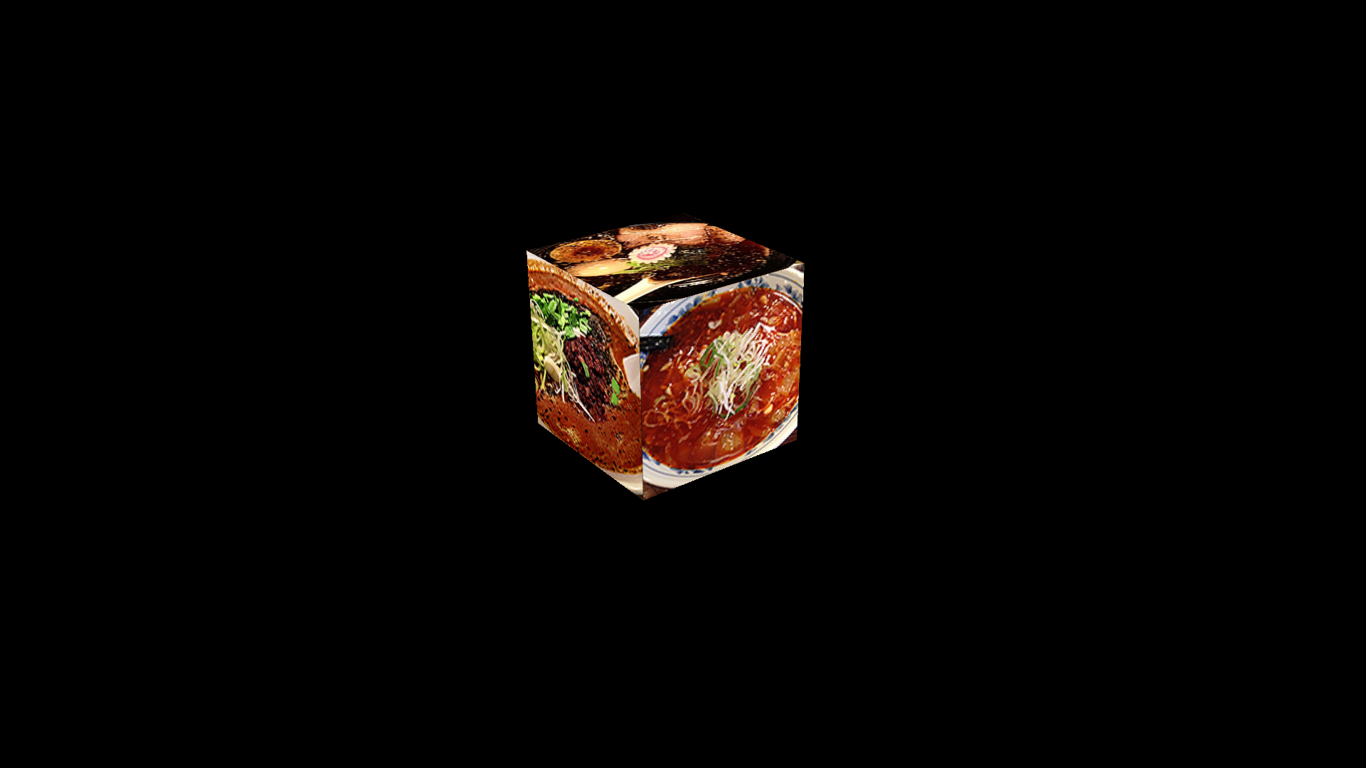
最后,我们将传入一个立方体的顶点坐标和纹理数据(只要你有其它模型的顶点坐标数据和纹理坐标,你都可以绘制),利用我们开发的 CustomPrimitive 模块来进行实例化,并添加到 Cesium 的场景当中。其中纹理坐标是为了能够将下面的纹理图贴到立方体的每个面上:

1 | // 位置数据说明 |
最后的效果如下图所示,项目的完整代码在这里: